HOW TO USE 3D JUUMP ACE TO VIEW CONTENT, CREATE VIEWS OF INDIVIDUAL PARTS OR ASSEMBLIES.
In this tutorial, see the use views in 3D Juump Ace to communicate and exchange 3D data with a colleague, customer or supplier.
Learn how to create different points of view on this data set and associate measurements, materials, colors or cut plans.
Tutorial in French with English subtitles.
User Guide:
4 - Edition panel
The Edition panel lets you select and define views in the View box, explore and change parts visibility in the Product structure or use the authoring tools in the Tool box to create new content.
4.1 - View box
The View Box groups the features that allows you to interact with the Thumbnail and 3D view mechanisms.
A right click on the thumbnail displays a context menu.
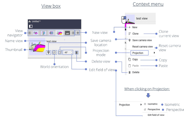
Users are free to create any number of views for a given project. However, only one view may be active at once: this view is referred to as the current view. Any change to the camera, part (transformation or material), cut plane or measurement is stored in the current view. In the View widget, the user can activate and manage Views.
- View navigator: Navigate between the different existing views.
- Name view: Create / Edit the name of the current view. Any created view is given the default name “Untitled view”. To rename views, click on their name text field.
- Thumbnail: Small picture that shows the content of the related View from a given point of view; it can also be used to recenter a saved 3D view.
- World orientation: Align the world with an object. To set the world orientation, click on the compass icon in the status bar, then select one or several objects to be aligned with the world’s frame. Upon selecting parts, a pop-up message appears at the bottom of the 3D view asking for the user to confirm the new orientation. Click the Validate button to apply the new world orientation or click on the compass icon again to discard changes.
- New view: Create a new view with default parameters.
- Save camera location: Save camera position and orientation to the current view, this operation creates/modifies the thumbnail.
- Projection mode: Select either an isometric or a perspective view.
- Delete view: Delete current view.
- Edit field of view: In perspective projection mode, adjust the vertical field of view.
- Clone current view: Create a new view with the same parameters as the current view.
- Reset camera view: Reset the camera view in the thumbnail.
- Copy: Copy the current camera view.
- Paste: Paste the copied camera view.
- Isometric: Projection in which exact views of an object are constructed by extending perpendiculars from points on the object to the plane of projection.
- Perspective: Projection of points by straight lines drawn through them from some given point to an intersection with the plane of projection
4.2 - Product structure box
The Product structure box shows the hierarchy of the project’s 3D data.
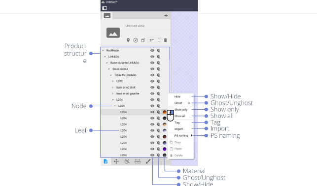
4.2.1 - Root Node
In this representation, each row element corresponds either to a node or to a leaf of the hierarchy. Nodes can be expanded or collapsed by clicking on the triangle icon located on the left of the product structure element.
- Node: Basic element of a hierarchy; using the image of a tree, a node is a branch.
- Leaf: Node on a tree with no child nodes.
- Material: Display the material of the corresponding part(s) (see Section: Materials tool).
Right-clicking on an element of the Product structure opens a context menu, which offers the following options:
- Show/Hide: Show or hide the corresponding part(s) in the 3D view.
- Ghost/Unghost: Enable/disable ghost rendering mode for the corresponding part(s).
- Show only: Hide every other part.
- Show all: Display all the elements.
- Tag: Create/Edit keyword assigned to a part.
- Import: Import a file at the same level as the selected part.
- PS naming: Select the text field to be displayed in the Mini-ID-card identifier. This content is previously input data.
- Selected element in the Product structure: Selecting an element in the Product structure also selects the corresponding part in the 3D view; its metadata is automatically displayed in the Mini-ID-Card.
- Reframed element in the Product structure: To center the camera on a designated element in the 3D view, on a designated element, double- click on the element in the Product structure.