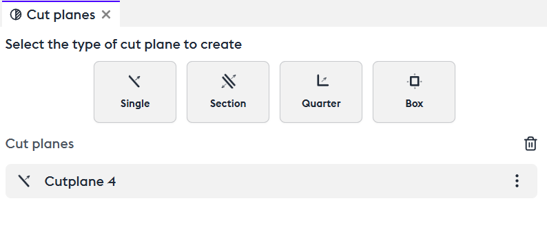
The Different Types of Cut Planes
Manipulation
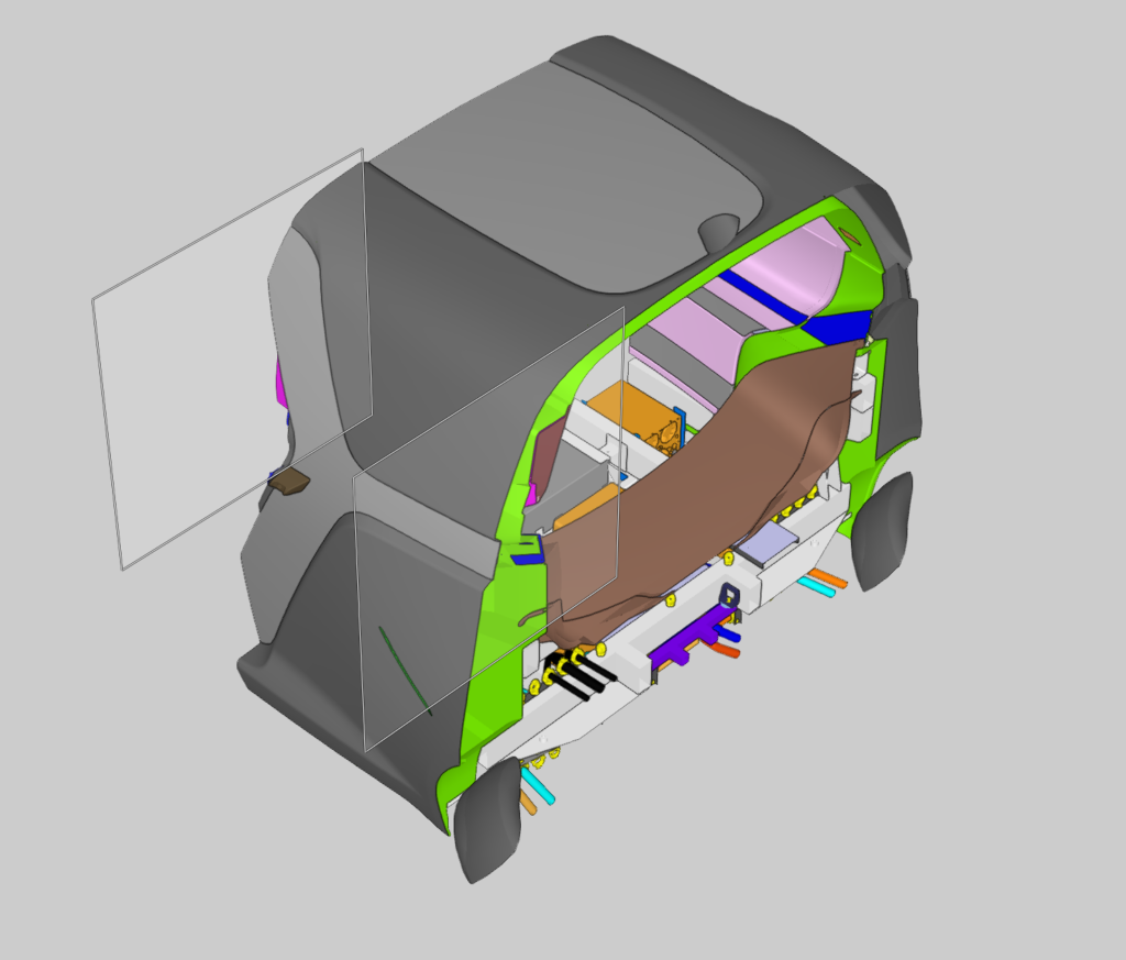
The cut plane is used to slice all or part of the assembly to make it easier to understand.
Create a single cut plane (“Single”). You can choose its orientation directly in the 3D view or in the control panel on the X, Y, Z axes, or via free selection.
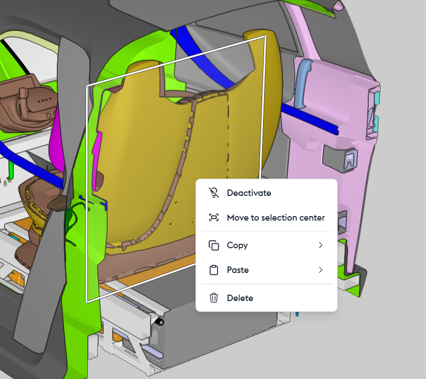
By right-clicking in the 3D view or accessing the options in the control panel (“cut plane”), you can enable/disable the cut plane (“Deactivate”), move it closer to the selected part to make it easier to manipulate (“Move to selection center”), copy/paste it (“Copy/paste”), or delete it (“Delete”).
The section allows you to create a double cut plane to isolate a specific section of the assembly. The distance between the cut planes is configurable in the control panel.
The quarter cut creates a quarter or three-quarter view that can be freely oriented.
The box is similar to the section, but with both vertical AND horizontal cuts, creating a box view. The spacing of the cut planes is configurable in the control panel.
Advanced Manipulation
Excluding/Including a Set of Parts
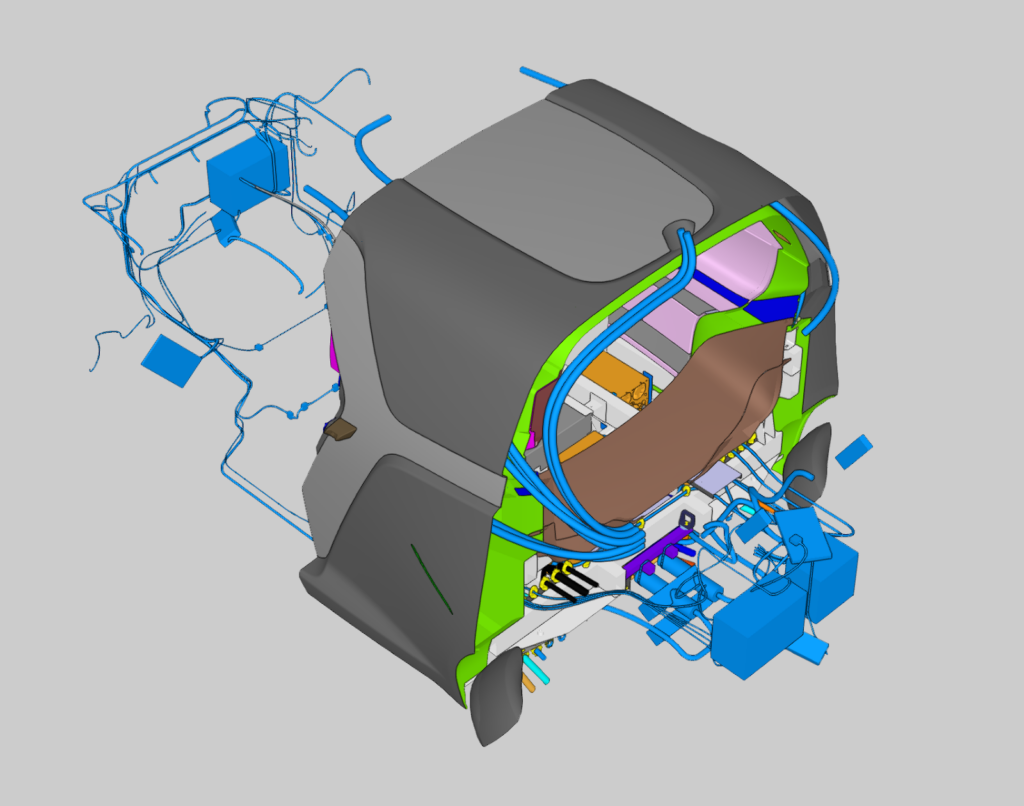
To visualize a specific part of the model without isolating everything that gets cut, you can exclude a selected group from the cut.
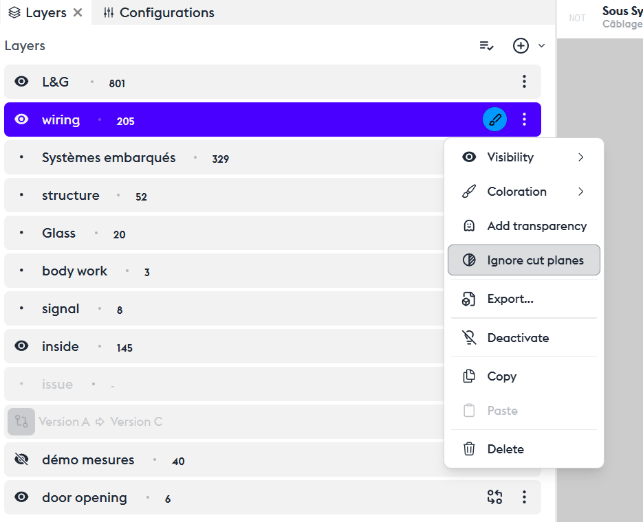
You’ll need to use layers to define a set of attributes.
To do this, create a new layer or choose an existing one, then add a filter to select a group of parts. For example, here we choose subsystems like the wiring and the interior body of the vehicle.
Use the context menu of the layer, then click on “Ignore Cut Planes,” and everything included in this filter will not be affected by the cut.