The General Idea
Layers are a key concept in scene composition. They allow you to group sets of parts, apply visualization attributes, actions (transformations), and combine them to create a scene. This scene can be replayed and duplicated or adapted as needed.
Each layer works with filters ([link to filter tutorial]). We encourage you to watch the dedicated tutorial, as filters and layers are inseparable when organizing your views.
Just like filters, layers allow you to add, subtract, or combine sets. Layers are also used to apply an action to a set of parts (transformations, coloring, etc.).
The philosophy behind layers is to provide flexibility in view creation. It is entirely possible to use only filters within a single layer, but this limits visualization potential.
Layer hierarchy operates from bottom to top—meaning lower layers take priority and are visible.
Best practice? Perform all your actions through the creation of a layer, as layers are intuitive and easy to identify.
Create a Layer
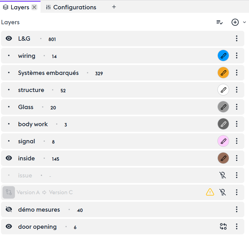
The first step is to create a layer. By default, this layer contains all the parts of your model. Using filters, you can create and isolate sets within this layer. For example, start with the exterior: the structure, the chassis, and the running gear.
The different states of the layer: mandatory visible / hidden / Does not affect visibility.
- The first action is to create a layer.
- By default, it contains all the parts of your model. Thanks to filters, you can already create and isolate sets within this layer—for example, the exterior first: the structure, the chassis, and the running gear. Layers also allow this segmentation but offer other very flexible options.
- To begin, let’s create a layer and place it at the top of the list, since layers are read from top to bottom. By default, it contains all the parts of your model. Thanks to filters, you can already create and isolate sets within this layer. We encourage you to read the tutorial dedicated to filters.
- The first step is to understand the different states of a layer: when its content is visible, when its content is hidden, or when its content does not affect visibility.
Visibility
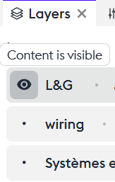
Content is visible
After adding a set of parts to a layer, you can choose to make it visible (“Content is visible”), which displays only that layer on screen—provided that no other layers affect the view.
Content is hidden
You can choose to make this set invisible (“Content is hidden”). This hides the elements of the layer, making everything that is not included in that layer visible again.
Does not affect visibility
And most importantly, you can choose not to affect visibility while still using the attributes of the layer (“Does not affect visibility”). This concept is essential, because actions applied to the layer will take effect without influencing the visualization of the rest of the model.
Layers options
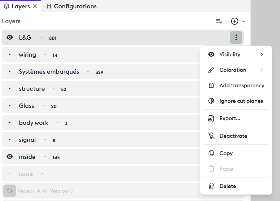
Coloring
The “Coloring” tool allows you to apply a reference color to the parts contained in this layer. By default, the color is red, and you can change it by clicking the “brush” icon to open the color editor. You can assign a color of your choice using the Hex code or the color palette. The available colors are those you have defined in your settings.
Adding Transparency (ghost)
You can choose to apply transparency to your layer. While making wiring transparent isn’t particularly useful, applying transparency to the layer containing the entire model (e.g., the “L&G” layer) can enhance visualization.
The “Add Transparency” tool allows you to make your layer transparent.
Ignore Cut Planes
The “Cut Planes” tool affects the ENTIRE model by default. The “Ignore cutplane” function prevents the section from being applied to this layer.
Export
If this configuration suits you, you can export the layer in a 3D format directly from its menu. The export dialog then opens, allowing you to export the set in the most common 3D formats. When exporting from a layer, the export will contain only what is included in that layer. If you want to export the complete model, you must use the overall 3D export tool. See the export dedicated tutorial.
Deactivate
You can choose to temporarily or permanently disable your layer. Its content is no longer visible or active.
Copy/Paste
You can duplicate your layer. It can then serve as a working base or a variant by applying other attributes to it. You can also copy this layer and paste it into another asset or another application of the suite, such as 3D Juump Kiwi.
Delete
You can also delete the layer.
Using a Layer for Transformations
Any transformation applied to a set of parts requires creating a layer beforehand. This means you must specify which parts will be subject to movement or measurement.
Specific layers
A Philosophy: Selecting by Theme
This is not strictly a specific tool, but it is an interesting concept to introduce the suite: you can select a set of parts for various reasons that are not only related to the nature of the part, but also to its state at a given moment. For example, if the model includes a list of parts that are problematic or require monitoring, you can create a dedicated layer for these issues.
Here, let’s create an “Issue” layer that will allow us to identify problems flagged with the label Issue “C”. We can choose to display them alone or to color them within a larger set in order to easily identify them.
Compare Two Distinct Configurations (Configuration Comparison)

In the layer menu, you have the option to create a configuration comparison layer. When adding this layer, a dialog box appears showing the list of product configurations. Let’s take version A (the one we’re working on) and compare it with version C.
We notice that most issues from version A have been resolved in version C. Only the rear shock absorbers still need revision.
Coloring by Value
This feature lets you quickly identify different types of sets. For example, you can color by system, subsystem, or part number. Adding a cut plane lets you quickly visualize these sets. You can interact with each group by clicking its folder in the layer. The same edit options available for standard layers will appear.
Grouped Actions (Layers Menu)
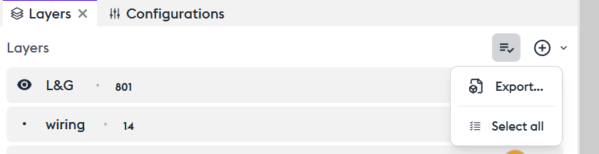
You can apply actions to multiple layers at once:
You can export them all (“Export”), select all (“Select All”), deselect all (“Deselect All”), or apply any individual action mentioned above to the entire selection (“Action on selection”).