Table of Contents
Create and import
Connection
On your web browser, log in to the 3D Juump applications login page using your username and password.
You will then access your personal 3Djuump space.
Selecting a Project
The 3D Juump applications are grouped on the homepage. Click on one of them to access it.
The welcome page of the selected application displays the available 3D models. These are integrated by your administrator or integrator.
The second dropdown menu offers the different versions of the product. Again, only the administrator and/or integrator have access to this data.
A third panel offers the different configurations of the product.
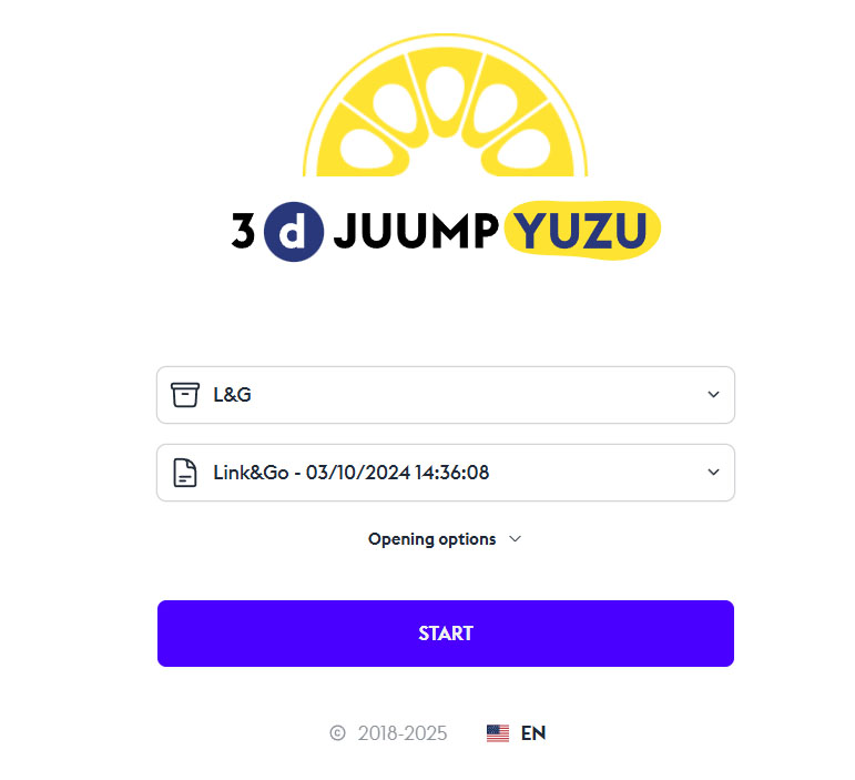
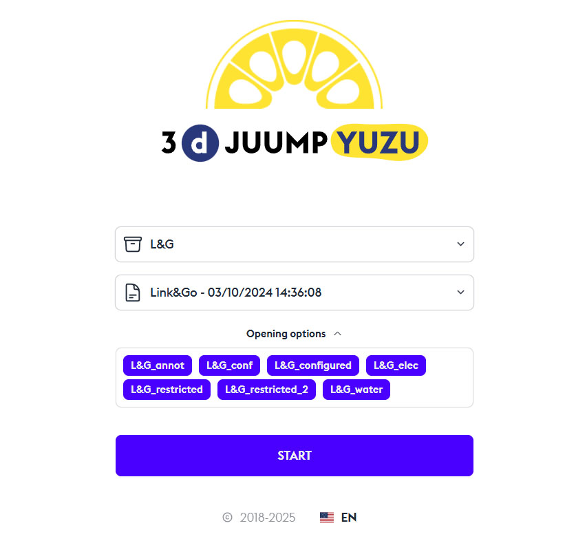
Press the Start button to begin.
Start
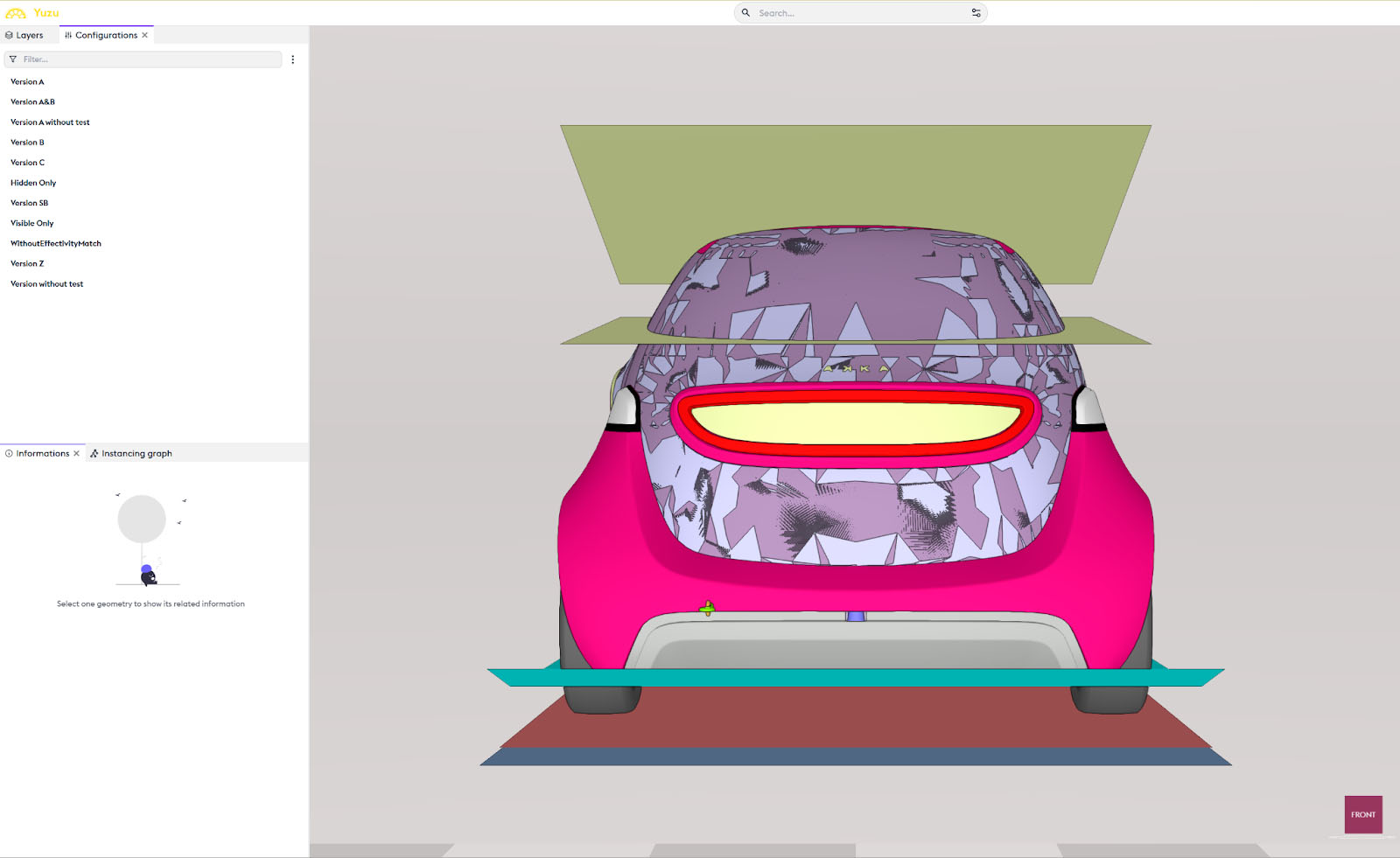
The original model, in its defined version and chosen configuration, then opens with all parts visible. This viewable model is grouped by default in a Layer. If filters are already present, they have been created by the administrator or integrator.
Modify the Configuration
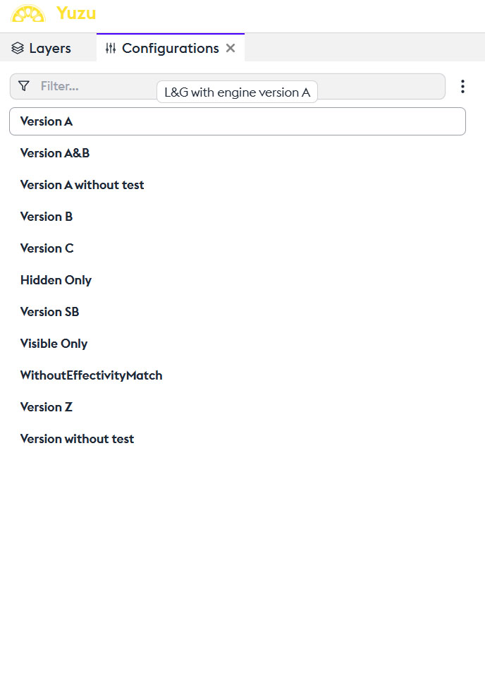
The configurations of the model are viewable and modifiable in the “Configurations” panel. You can isolate or combine them.
Importing an Existing Project
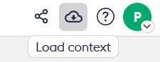
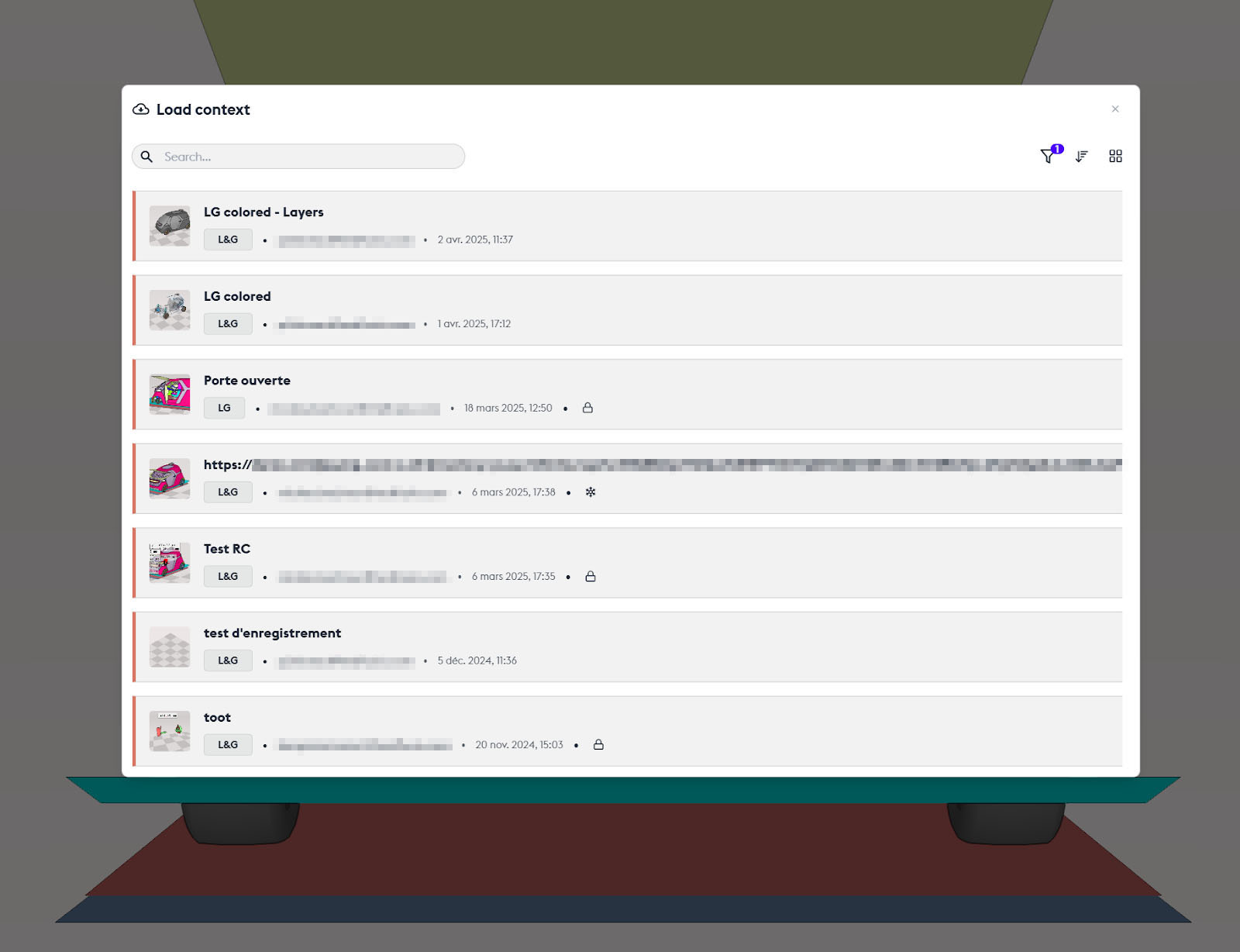
By clicking on the management menu at the top right, you have the option to load an existing build (“context”). You then access a summary of the Asset Manager, where you can perform a search. You open the project by double-clicking on it.
Asset Manager
The Asset Manager groups the projects of your company or team. Each project has options, usable according to your status: administrator, project creator, or simple consultant (affiliated collaborator). It also offers traceability of projects and management of access rights.
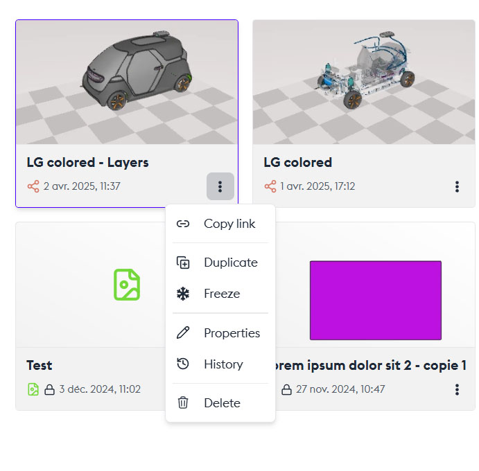
Asset Options
The “Copy Link” option allows you to copy the asset’s address. This allows you to send it for consultation to the contact of your choice.
Duplicate
The “Duplicate” option allows you to duplicate the asset. For example, if you want to start another asset from the previous one.
Freeze
This is an archiving at a specific moment. The asset is frozen, and only the administrator can change its state.
Properties
The “Properties” option allows you to access the asset’s information. Its name, description, tags, access rights (“Access Rights”) which can be defined by its creator or the administrator under 3 types of access: “Can edit” which allows any user to modify this asset. “Can view” which allows users to view the asset without making any changes to it. And “No right” which does not allow any intervention on this asset: the asset exists but access is denied to part of the team.
Security Tags
Security tags provide access rights to certain 3D data and metadata. Some parts are inaccessible or invisible as long as the user does not have the appropriate security tags.
You can also add a comment on the asset.
History
The “History” option opens an exploration box that details all changes and access to the asset. With the name of the build, the identity of the user or creator, and the security tags.
Delete
The “Delete” option allows you to permanently delete the asset.
Double-click on the asset
Allows you to open it.
3D Navigation
Different Navigation Modes
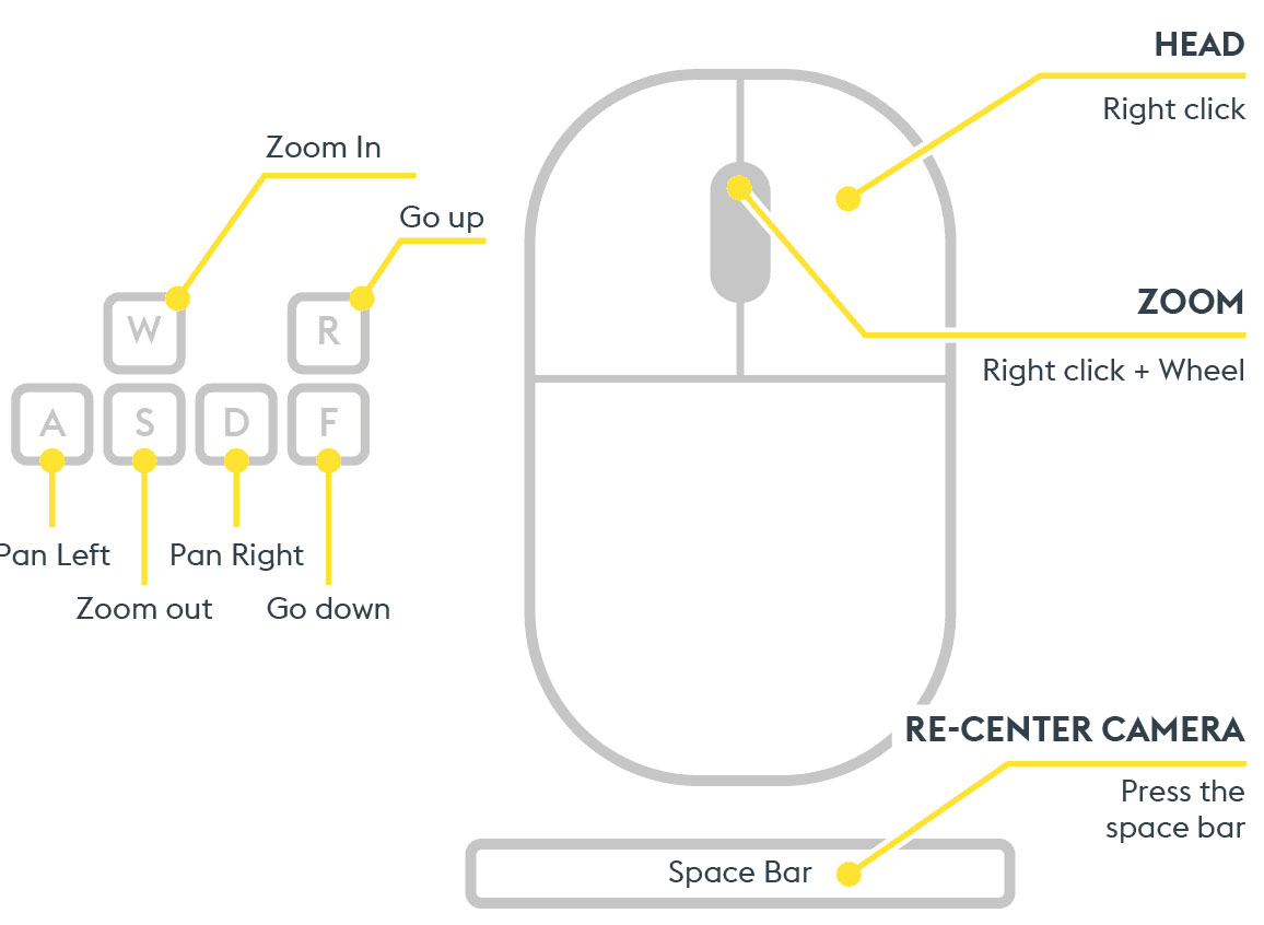
There are three navigation modes: Orbital, Examine Mode, and Fly Mode. By default, the orbital mode is selected. It is the most intuitive for basic use. For more information on the modes, we suggest you watch the discovery tour, available at the software’s opening and in the Help menu, which describes the functions of the keys for each mode.
Press the Start button to begin.
Moving in 3D
The Central Navigation Point
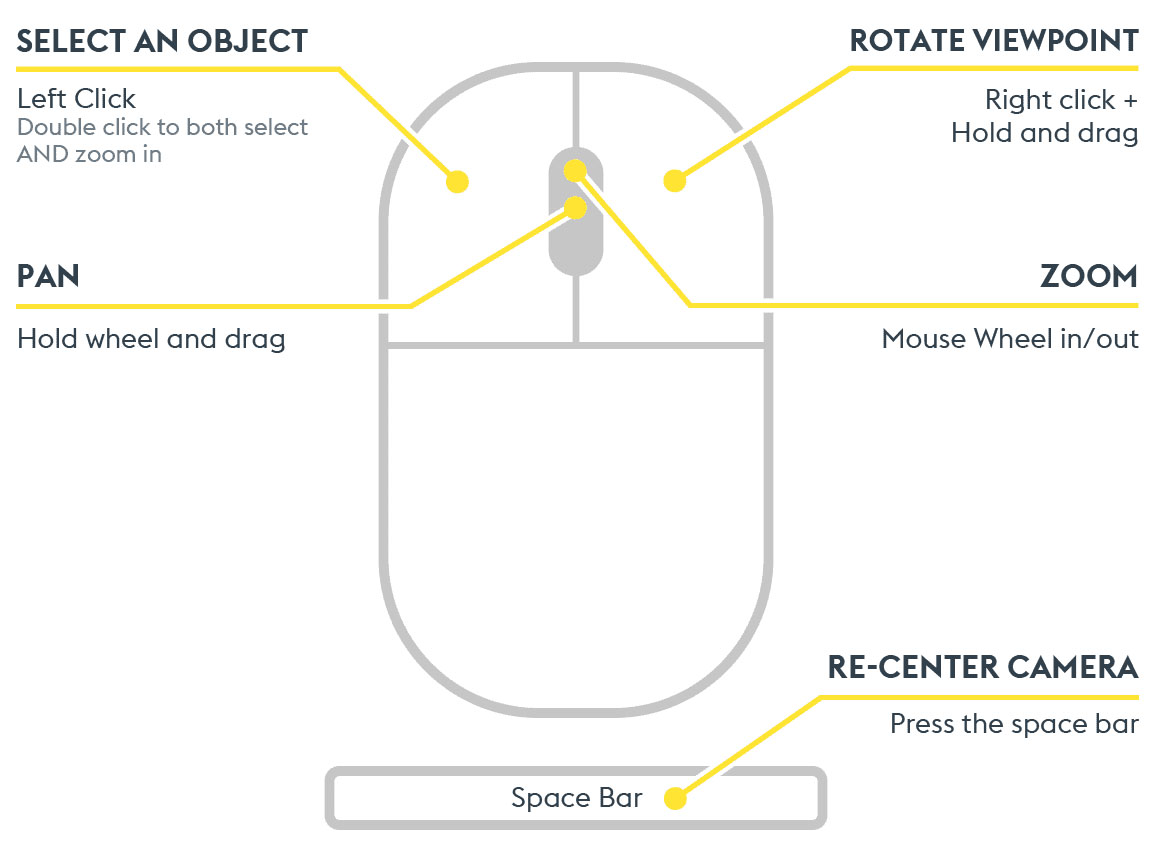
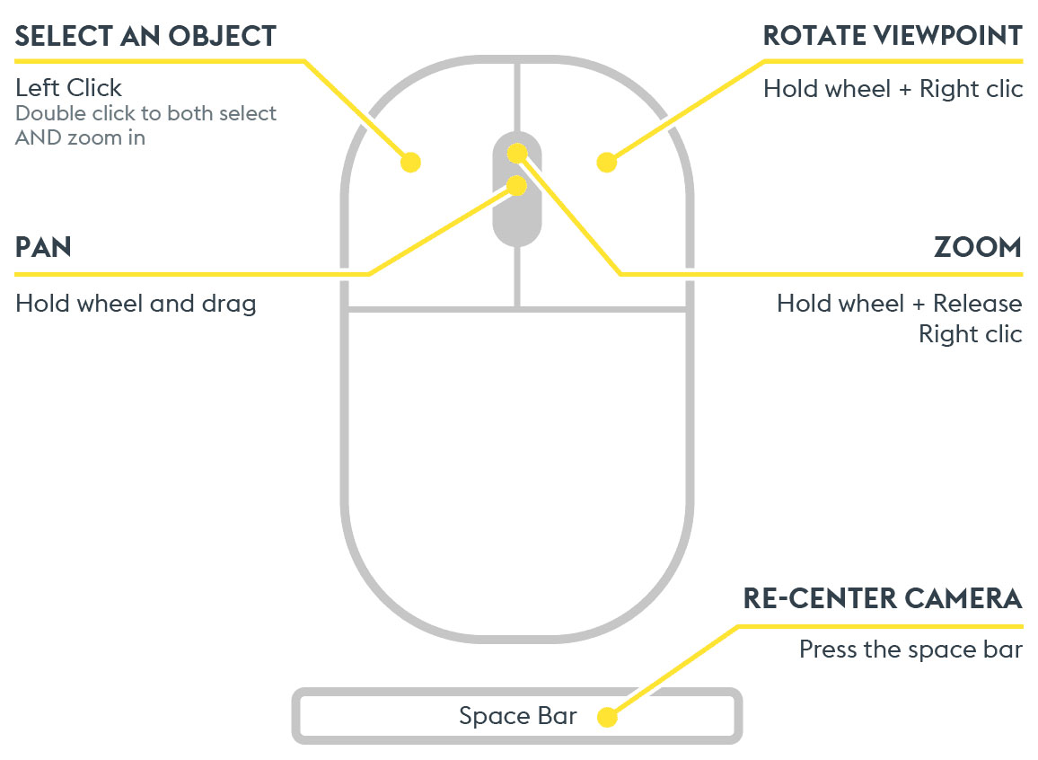
In orbital mode, you can select a central navigation point either by clicking the mouse wheel or by right-clicking/set navigation center. This will set the point around which your camera will move. Scrolling the wheel forward will zoom in on this point, and scrolling backward will move away from the point. Selecting a part with a simple left-click places the central navigation point on that part.
Orientation
Orientation is done by holding the right-click, then moving the mouse.
Translation
Translation (pan) is done by holding the mouse wheel and moving the mouse.
The Cube
The cube allows for strict orientation of the camera. Simply click on a face, a corner, or an edge to automatically orient the scene.
A single press on the mouse wheel places the centre point of navigation at the desired location.
Approaching
Tips
Zoom: Mouse wheel forward/backward
Smooth Zoom: Hold the wheel + Ctrl + move the mouse forward
For a quick approach, you can use the space bar, which will center the view on this point. This is also the function of the “fit to selection” button.
Double click a part for a quick approach to it.
Conversely, the “See all visible geometries” button allows you to replace the model at the center of the scene, moving away from the part.
The “Activate zoom mode by marquee” button allows you to select an area and approach it. When this is activated, simply select an area with the left mouse click, hold, and expand or reduce the selection area. It automatically deselects after use.
Orthographic projection is a representation without perspective, with real dimensions for technical drawing.
Perspective projection creates an illusion of depth, used for realistic renderings.
Visualizing
To better visualize a hidden part, you can use the “isolate mode” button. This allows you to ghost the parts that are not selected, in order to visually isolate your selected part.
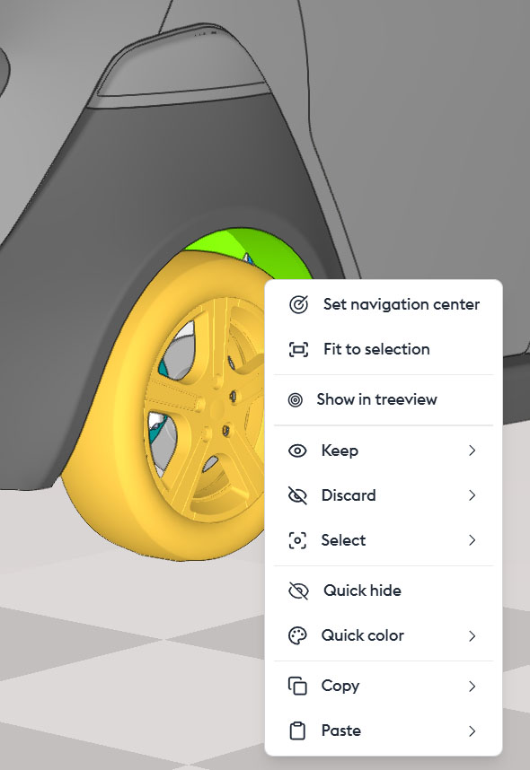
The Contextual Menu of the Parts
A right-click on a part opens a contextual menu, from which several actions are possible:
- Set to navigation center: Allows you to set the central point of navigation.
- Fit to selection: Allows you to get closer to the part.
- Show in treeview: Allows you to select the part in the treeview.
Keep/…: Allows you to create a filter that will be added to an existing layer or a new layer. Please note that only metadata checked in the favorite fields of the ID Card (of any part) can be used to create a layer. If the layer creation option does not appear, it is most likely due to the absence of selected metadata.
- Discard/…: Allows you to create a layer with the chosen name and force its state to “invisible.” Useful for hiding a part or a set.
- Select/…: Allows you to create a layer with the chosen name and force its state to “inactive.” Useful for coloring, for example.
Quick Actions
“Quick Hide” or Delete allows you to instantly hide a part. You can undo this action right away. You can also inspect all hidden parts in the “Hidden Geometry Space“, and make them reappear by performing the inverse operation — that is, showing the geometry.
“Quick Coloration“
allows you to quickly apply color to a part on the fly. The “Quick Coloration” button removes the temporary coloring and restores the original color. It’s not possible to choose which parts are affected: all parts will revert to their original color.
For this reason, using quick coloration is not recommended for long-term projects. Instead, you should use layers.
However, it’s possible to restore the original color of a single part by right-clicking → Quick Coloration → Reset Color.
Warning: These actions will not be replayed if the build changes or if you share your model. They are for temporary or illustrative use only. They will be saved in your view, but won’t be reapplied if the model evolves or is sent to someone else.
- Copy: Allows you to copy a context.
- Paste: Allows you to paste a context, into another application, for example.
Miscellaneous (bottom right menu)
The “Configurations” button allows you to quickly switch from one version to another of your model. If it was created with multiple configurations, you can display them here to compare or work on another version.
The “Quick Hide” button offers the possibility to switch to the “hidden world,” the display space for parts that have been hidden on the fly. You can choose to make some or all of them appear in the “visible world.”
The “Quick Coloration” button allows you to remove on-the-fly colorization, returning to the original color. It is not possible to choose which parts will be affected: all parts will return to their original color. This is why it is not recommended to use quick coloring for long-term projects. You should use layers instead. However, it is possible to return to the original color of a single part by right-clicking/quick coloration/reset color.

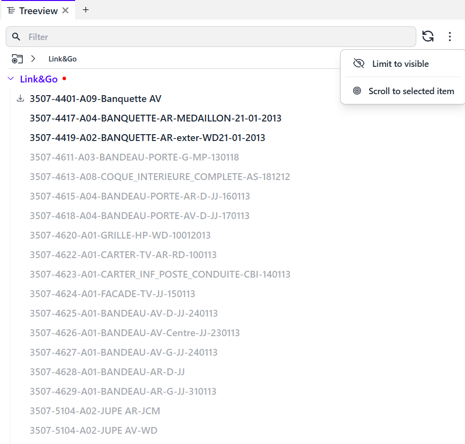
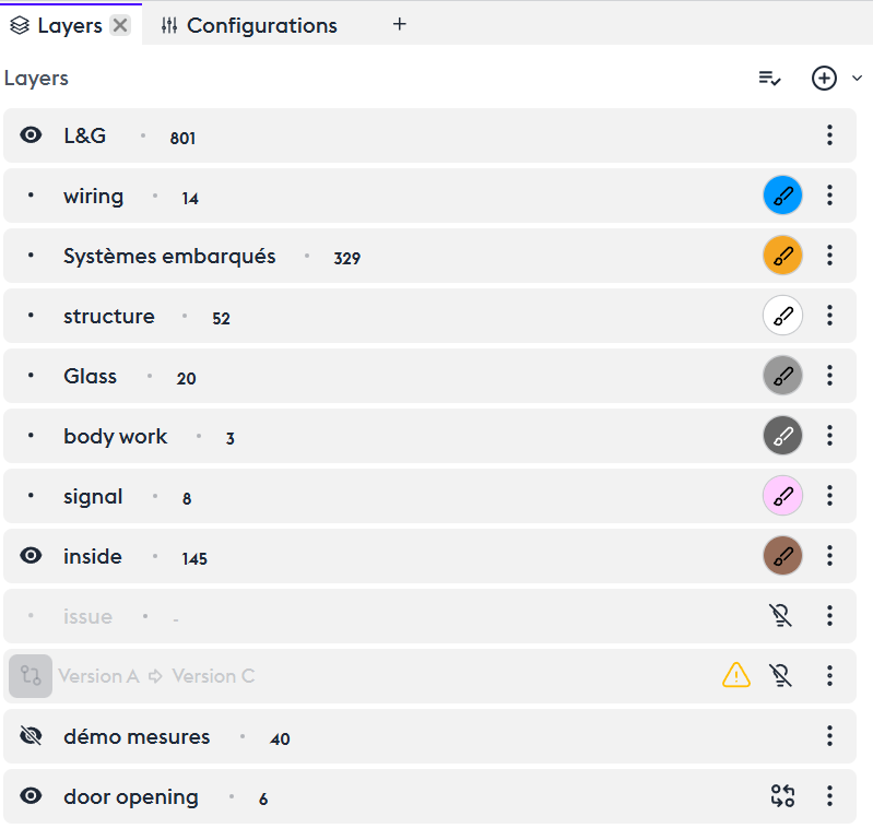
Treeview
The tree view displays the complete structure of your model. Click on a part in the 3D view and the treeview will display its name and position in the structure.
For performance reasons, the treeview does not display all parent parts by default. This is done on demand.
Non-visible parts are automatically grayed out to facilitate reading. (Expand the L&G node to illustrate)
If you wish to display only the visible parts, simply click the option at the top right of the window (“limit to visible“).
If you want to display only the parts related to a specific configuration, select the “limit to configuration” option.
In very detailed treeviews, the display of the part may appear truncated. Find it by clicking “Scroll to selected item.”
Right-clicking on a part in the tree view offers most of the same options as right-clicking on a 3D part or its information card.
This opens a context menu, from which several actions are available:
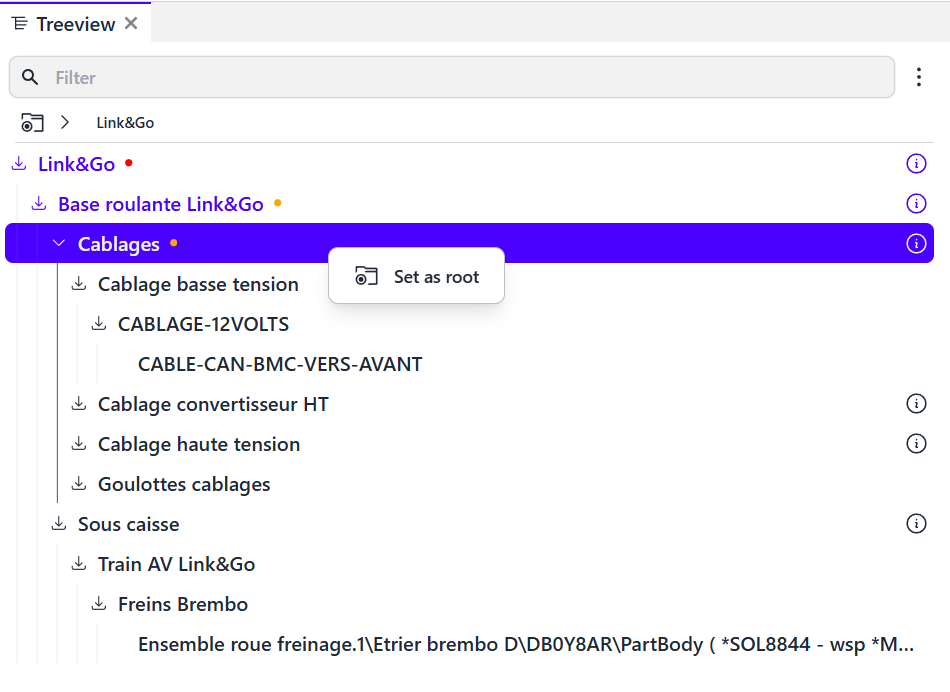
Set as root node
Helps clarify the tree view by defining a group of parts as your working context.
For specialized workflows, it’s possible to set a subsystem as the root node to focus only on that topic (right-click on the node, then “Set as root node”). This places the node at the top of the tree view. You can always return to the main root by clicking the breadcrumb at the top of the window.
Set as navigation center
Defines the central point for navigation.
Fit to selection
Zooms in on the selected part.
Keep /...
Allows you to retain a part within a filter that will be added to an existing layer or a new one.
Please note that only metadata checked in the favorite fields of the ID Card (of any part) can be used to create a layer. If the layer creation option does not appear, it is most likely due to the absence of selected metadata.
Reject /...
Creates a layer with the name of your choice and forces its state to “invisible”. Useful for hiding a part or group.
Select /...
Creates a layer with the name of your choice and sets its state to “does not affect visibility”. Useful, for example, for coloring.
Quick actions
(“Quick hide” and “Quick color”)
Allow you to instantly hide a part (which will appear in the “hidden geometries space”) or quickly apply a color to it.
These actions will not be replayed if the build changes or if you share your model. They are for temporary or illustrative use only. They will be saved in your view, but won’t be reapplied if the model evolves or is sent to someone else.
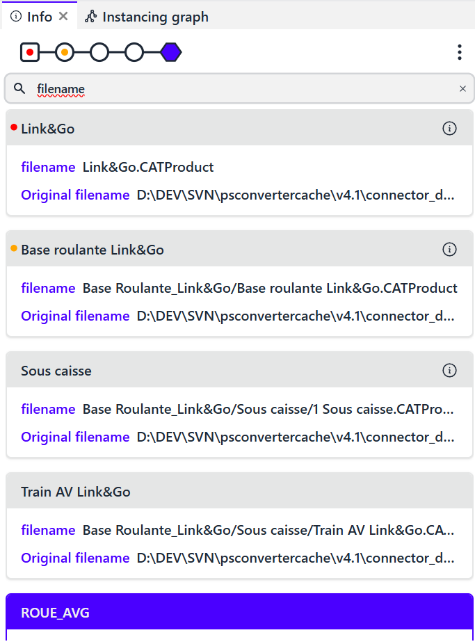
ID Cards
The information card displays all metadata associated with a part or system.
Presentation
Part Information
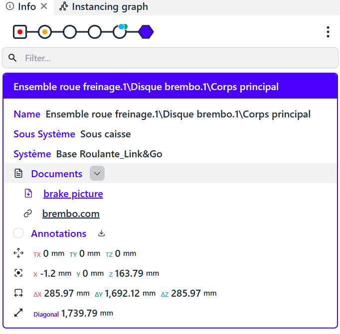
By default, the information sheet of a part presents the main metadata from the model, chosen by the model integrator:
- Name
- Subsystem
- System
It also presents geometric and positioning information:
- Its position (the translation of the part relative to its parent)
- The center of its bounding box
- The dimension of its bounding box
- The diameter of the sphere that encloses it
Metadata and Enriched Data
Metadata can be complex objects: they can be enriched with tables, comments, links, keywords, or various indications. These are implemented by the designer and/or the model integrator.

Press the Start button to begin.
It is possible to attach documents (integrator rights) to the metadata, such as a photo of the part for download or in HTML or pre-recorded annotations by the integrator.
Hierarchy
It is possible to trace the hierarchy of each part to identify or select the set to which it belongs by clicking on the nodes of its branch.
Additional Information
Some nodes have colored badges. The blue badge indicates the presence of an attached document. The green badge indicates one or more annotations.
Display Choices (Custom GUI)
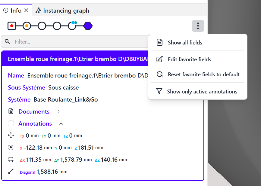
Show All Fields
You can choose to display all the information about the part and its hierarchy in the product structure. You then get all the available information.
Edit Favorite Fields
You can decide which important information the sheet should show by clicking on “Edit Favorite Fields.” This action will apply to all ID cards of the parts in the model and will be retained during future consultations.
Reset favorite fields to default
This allows only the information integrated by the administrator to be displayed.
Show only Active Annotations
You can decide to show all or part of the annotations inserted in the model by clicking on the appropriate button.
Quick Filtering
The display of metadata can be abundant. You can choose to quickly filter information by characteristics or attributes. For example, “name” allows you to display only the name of the part.
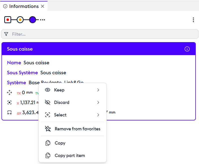
Context Menu
A right-click on a mention of the information card opens a context menu, offering several options.
Right-click on a name, subsystem, or system:
- Keep/…: Allows you to keep a part within a filter that will be added to an existing layer or a new layer.
- Please note that only metadata checked in the favorite fields of the ID Card (of any part) can be used to create a layer. If the layer creation option does not appear, it is most likely due to the absence of selected metadata.
- Discard/…: Allows you to create a layer of your choice and set its state to "invisible." This is useful for hiding a part or a set.
- Select/…: Allows you to create a layer of your choice and set its state to "inactive." This is useful for coloring, for example.
- Remove from Favorites: Allows you to manage the number of information items present on the card. These fields can be edited in the editor, available in the top-right menu of the "information" panel.
- Copy: Allows you to copy the name
- Copy part item: Allows you to copy all the part informations
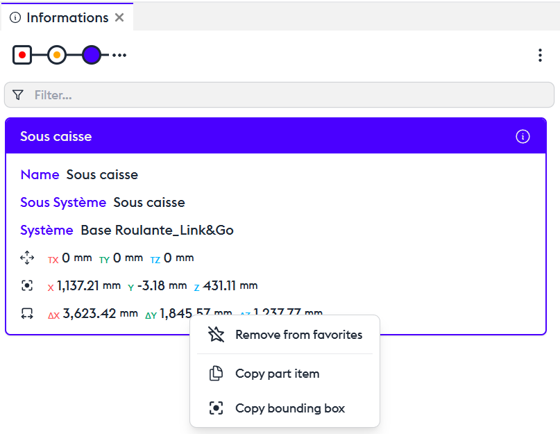
Right-click on a measurement or transformation:
- Remove from Favorites: Allows you to remove the information present on the card. These fields can be edited in the editor, available in the top-right menu of the "information" panel.
- Copy Element: Allows you to copy the values to duplicate them in a text file or spreadsheet.
Search
Simple Search
The search tool operates intuitively like a search engine.
In simple search mode, the engine will search through all metadata for results that contain the query.
In the 3D view, by default, the results are displayed by isolating them from the other parts. They may appear as markers, with or without a ghost environment (semi-transparent), depending on the display options you selected in the search engine.
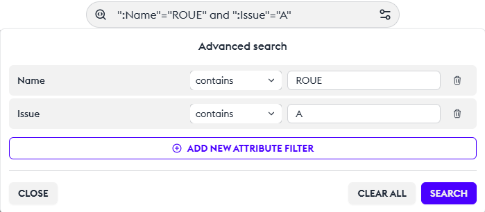
Advanced Search
There is an advanced search editor for constructing complex and cross-referenced searches. You can configure your search editor according to your needs.
You can choose exact or contained results, and you can add filters by “issue,” “date” or any information from the metadata. Each search is saved in the history.
Apply This Search to the 3D Scene
If the cross-referenced search meets your needs, you can directly apply this selection by clicking on “Convert Search to Filter.” This will create an automatic filter on the active layer, instantly filtering your context.
Visibility of Parts
By default, the search only works on visible parts (as defined by the layers). Therefore, the search result might be empty, or you might not find your part. You have the option to override this limitation and perform a global search on all parts of the model using the option in the context menu “extend search to all mockup” An icon will indicate that this part is currently hidden.
Number of Recurring Results
The engine can indicate the number of parts that have the same name or the same metadata. If an object is duplicated in the model, you will know its exact number by looking at the dropdown menu.
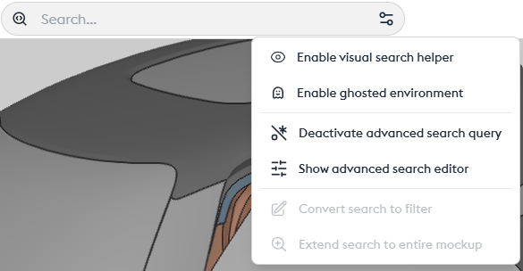
Different Options in the Context Menu
- Disable visual search aid: Removes the badges locating each object in the search.
- Disable ghost environment: Allows removing the ghost view (transparency). Parts included in the search will still be visible, but any other parts in transparency will be excluded from the view.
- Enable/Disable advanced search queries: Allows adding RegEx (regular expressions) queries. Reserved for advanced users.
- Show advanced search editor: Allows displaying the editor and compiling a cross-referenced/complex search without having to master regular expression syntax.
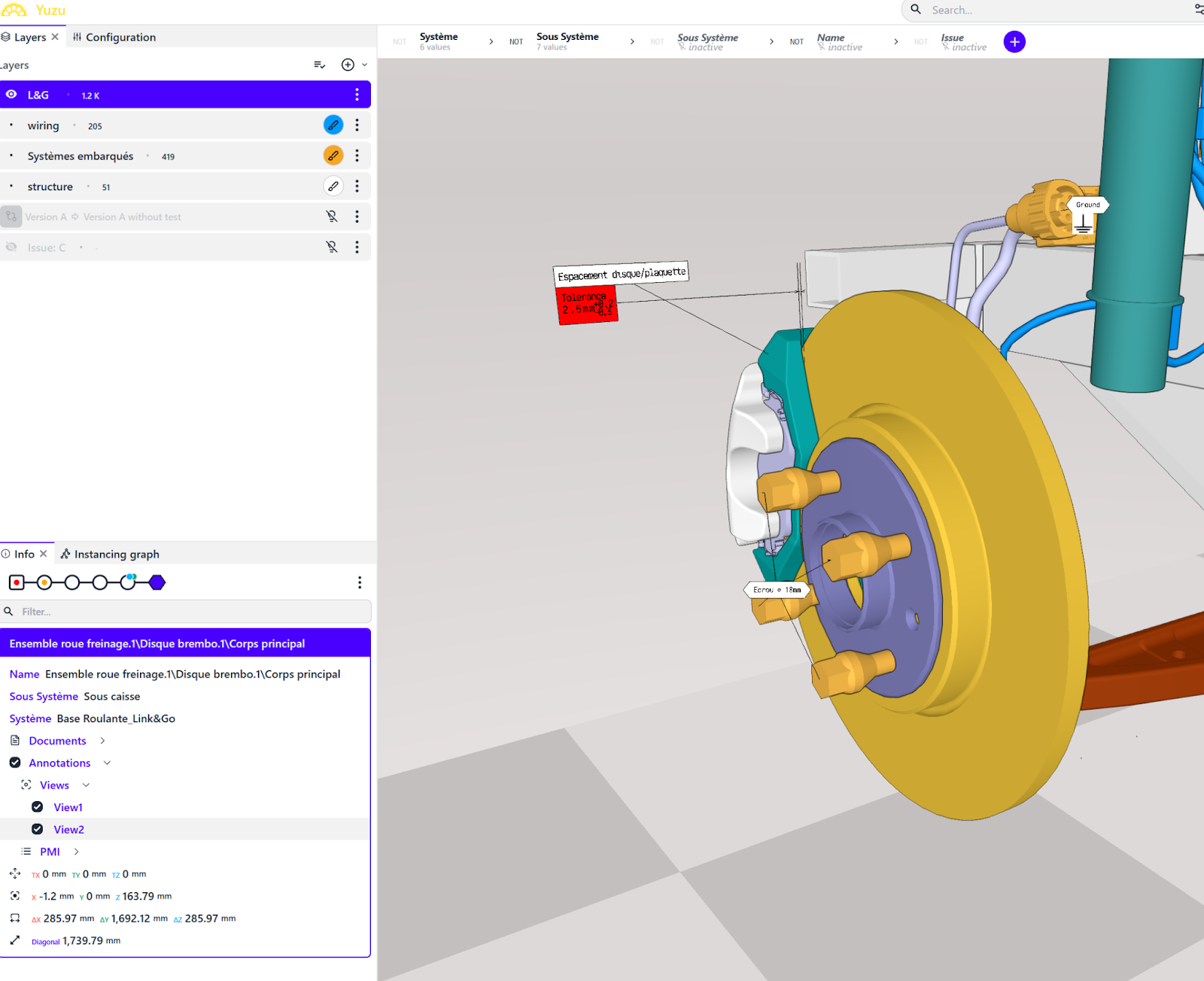
Layers
The General Idea
Layers are a key concept in scene composition. They allow you to group sets of parts, apply visualization attributes, actions (transformations), and combine them to create a scene. This scene can be replayed and duplicated or adapted as needed.
Each layer works with filters ([link to filter tutorial]). We encourage you to watch the dedicated tutorial, as filters and layers are inseparable when organizing your views.
Just like filters, layers allow you to add, subtract, or combine sets. Layers are also used to apply an action to a set of parts (transformations, coloring, etc.).
The philosophy behind layers is to provide flexibility in view creation. It is entirely possible to use only filters within a single layer, but this limits visualization potential.
Layer hierarchy operates from bottom to top—meaning lower layers take priority and are visible.
Best practice? Perform all your actions through the creation of a layer, as layers are intuitive and easy to identify.
Create a Layer
The first step is to create a layer. By default, this layer contains all the parts of your model. Using filters, you can create and isolate sets within this layer. For example, start with the exterior: the structure, the chassis, and the running gear.
The different states of the layer: mandatory visible / hidden / Does not affect visibility.
- The first action is to create a layer.
- By default, it contains all the parts of your model. Thanks to filters, you can already create and isolate sets within this layer—for example, the exterior first: the structure, the chassis, and the running gear. Layers also allow this segmentation but offer other very flexible options.
- To begin, let’s create a layer and place it at the top of the list, since layers are read from top to bottom. By default, it contains all the parts of your model. Thanks to filters, you can already create and isolate sets within this layer. We encourage you to read the tutorial dedicated to filters.
- The first step is to understand the different states of a layer: when its content is visible, when its content is hidden, or when its content does not affect visibility.
Visibility
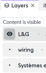
Content is visible
After adding a set of parts to a layer, you can choose to make it visible (“Content is visible”), which displays only that layer on screen—provided that no other layers affect the view.
Content is hidden
You can choose to make this set invisible (“Content is hidden”). This hides the elements of the layer, making everything that is not included in that layer visible again.
Does not affect visibility
And most importantly, you can choose not to affect visibility while still using the attributes of the layer (“Does not affect visibility”). This concept is essential, because actions applied to the layer will take effect without influencing the visualization of the rest of the model.
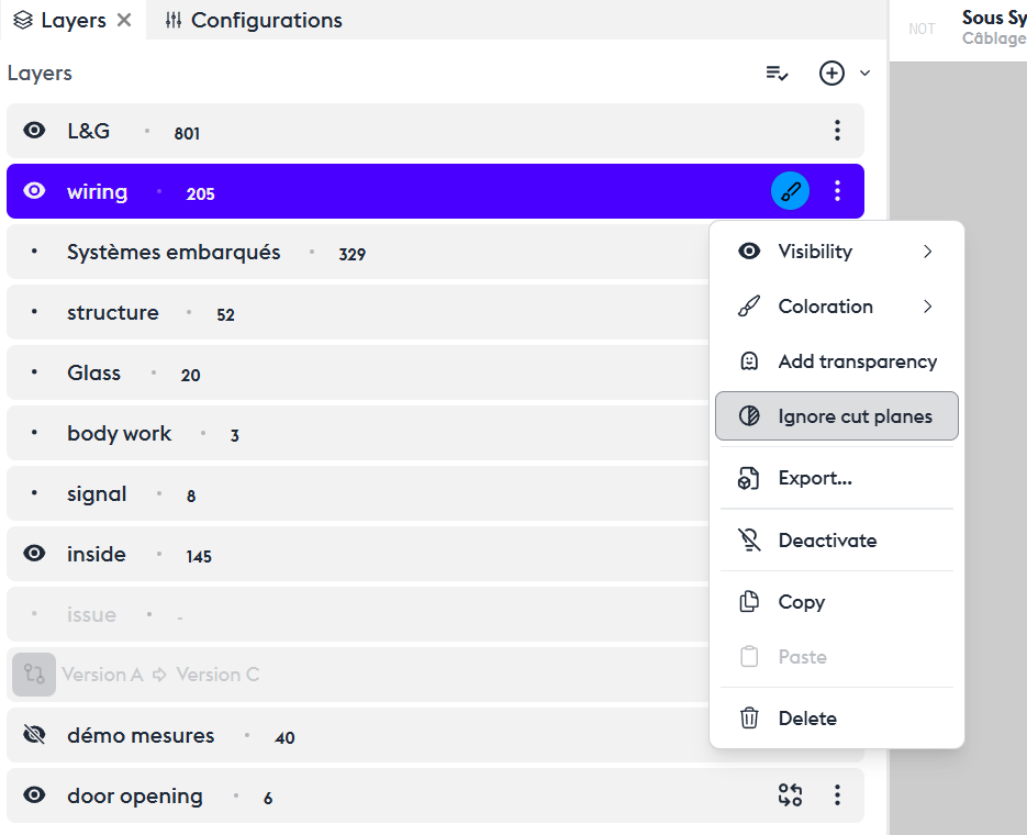
Layers options
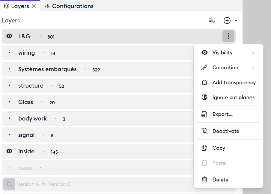
Coloring
The “Coloring” tool allows you to apply a reference color to the parts contained in this layer. By default, the color is red, and you can change it by clicking the “brush” icon to open the color editor. You can assign a color of your choice using the Hex code or the color palette. The available colors are those you have defined in your settings.
Adding Transparency (ghost)
You can choose to apply transparency to your layer. While making wiring transparent isn’t particularly useful, applying transparency to the layer containing the entire model (e.g., the “L&G” layer) can enhance visualization.
The “Add Transparency” tool allows you to make your layer transparent.
Ignore Cut Planes
The “Cut Planes” tool affects the ENTIRE model by default. The “Ignore cutplane” function prevents the section from being applied to this layer.
Export
If this configuration suits you, you can export the layer in a 3D format directly from its menu. The export dialog then opens, allowing you to export the set in the most common 3D formats. When exporting from a layer, the export will contain only what is included in that layer. If you want to export the complete model, you must use the overall 3D export tool. See the export dedicated tutorial.
Deactivate
You can choose to temporarily or permanently disable your layer. Its content is no longer visible or active.
Copy/Paste
You can duplicate your layer. It can then serve as a working base or a variant by applying other attributes to it. You can also copy this layer and paste it into another asset or another application of the suite, such as 3D Juump Kiwi.
Delete
You can also delete the layer.
Using a Layer for Transformations
Any transformation applied to a set of parts requires creating a layer beforehand. This means you must specify which parts will be subject to movement or measurement.
Specific layers
A Philosophy: Selecting by Theme
This is not strictly a specific tool, but it is an interesting concept to introduce the suite: you can select a set of parts for various reasons that are not only related to the nature of the part, but also to its state at a given moment. For example, if the model includes a list of parts that are problematic or require monitoring, you can create a dedicated layer for these issues.
Here, let’s create an “Issue” layer that will allow us to identify problems flagged with the label Issue “C”. We can choose to display them alone or to color them within a larger set in order to easily identify them.
Compare Two Distinct Configurations (Configuration Comparison)

In the layer menu, you have the option to create a configuration comparison layer. When adding this layer, a dialog box appears showing the list of product configurations. Let’s take version A (the one we’re working on) and compare it with version C.
We notice that most issues from version A have been resolved in version C. Only the rear shock absorbers still need revision.
Coloring by Value
This feature lets you quickly identify different types of sets. For example, you can color by system, subsystem, or part number. Adding a cut plane lets you quickly visualize these sets. You can interact with each group by clicking its folder in the layer. The same edit options available for standard layers will appear.
Grouped Actions (Layers Menu)
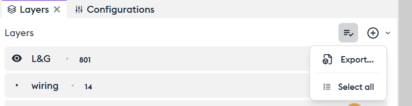
You can apply actions to multiple layers at once:
You can export them all (“Export”), select all (“Select All”), deselect all (“Deselect All”), or apply any individual action mentioned above to the entire selection (“Action on selection”).
Filters
General Philosophy : Add a Filter to Create a View
Create a Literral Filter to Display a View
The context of your model is based on adding multiple filters combined using operators.
These filters apply to a layer.
You can choose any existing metadata field — just some of them, or all at once.
You can check the number of parts contained in this layer using its badge, and select these parts by clicking on the badge.
Copy/Paste :
You can copy a filter from one layer to another, or within the same layer, by right-clicking in the filter bar and selecting Copy/Paste.
Create a Tag/Container

Tag Selection (Values): User Guide
The system allows you to select specific values using two types of tags:
- Blue tags: exact match
- Green tags: partial match (“contains”)
Tag Display
The available tags are displayed in a dedicated window.
If there are many values, infinite scrolling is enabled — additional tags load automatically as you scroll.
Blue Tags – Exact Match
These tags allow you to select values that match exactly.
Green Tags – Partial Match
These tags allow you to select values that contain the entered string, regardless of its position within the tag value.
Unlike blue tags, the search operates in “contains” mode — it finds tags even if the entered string appears in the middle or at the end.
This makes searching easier when you don’t know the exact beginning of the tag.
Tag Filtering
A filter field is available to narrow down tags.
The filtering engine uses a “starts with” rule and is case-sensitive — uppercase and lowercase letters must match exactly.
Example: to find TagExample, you must type Tag (not tag or Example).
Usage Tips
- Use blue tags when you know the exact beginning of the tag you’re looking for.
- Use green tags for more flexible searches, especially when you only know part of the tag.
- Remember to respect case sensitivity for blue tags; otherwise, no results will be displayed.
Types of Filters
Attributive Filter

To display all or part of the parts in the model, you can combine filters using inter-filter operators.
Intersection between two criteria identifies the parts that meet both conditions simultaneously.
In other words, it looks for cases where both criteria are true at the same time.
Exclusion works in the opposite way.
The view displays parts selected by the first filters while excluding those defined in the excluded filter.
Union adds the parts from the current filter to those already selected by previous filters, broadening the visualization.
YES/NOT Behavior
You can set a filter’s behavior to “NOT” to exclude the elements it contains.
For example, if you want to display all parts except those in the “Vis” filter, enable the “NOT” mode.
Active/Inactive Behavior
You can choose to activate or deactivate a filter’s effect depending on your temporary needs — for instance, to reveal certain parts of your model. This avoids having to delete a filter to disable it.
Filter Behaviors and Their Inter-Filter Operators
Inter-Filter Operators
The attributive filter is a filter that uses a specific metadata field and a list of values to calculate a set of geometric objects with those values. It allows you to select objects based on their properties.
Literal Filter
As shown before, this filter allows you to find parts or assemblies by typing words.
It works like the general search, so if you want to keep search results in a layer, just use this filter.
There’s also an option in the search tool called “Convert search to filter” to speed up the process.
Box Filter
This filter allows you to create a box by interacting directly with the 3D model.
Click on a part or assembly to include it in the box. Hold CTRL and click another part — the box will automatically expand to include it. You can modify the box size at any time, either by entering numeric values or directly in 3D using the Gizmo assistant.
The Gizmo has two modes: size or position, allowing you to adjust your box precisely.
Validate to obtain your filtered view.
Box Filter Variant: You can choose to include all objects that intersect the box or only those strictly contained within it.
Note: During box filter creation, all transformations applied to model parts (including those in other layers) are temporarily disabled.
Radius Filter
This filter allows you to select a group of parts based on their dimensions — more specifically, based on the radius of their bounding box.
It can be used to exclude non-essential parts (for example, to reduce polygon count) or, conversely, to identify parts for statistical purposes (count, weight, etc.).
Compound Filter
Cutplanes
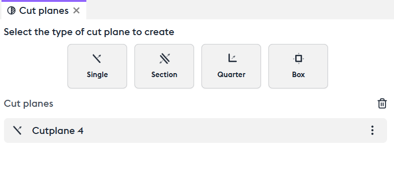
The Different Types of Cut Planes
Manipulation
The cut plane is used to slice all or part of the assembly to make it easier to understand.
Create a single cut plane (“Single”). You can choose its orientation directly in the 3D view or in the control panel on the X, Y, Z axes, or via free selection.
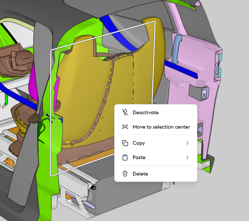
By right-clicking in the 3D view or accessing the options in the control panel (“cut plane”), you can enable/disable the cut plane (“Deactivate”), move it closer to the selected part to make it easier to manipulate (“Move to selection center”), copy/paste it (“Copy/paste”), or delete it (“Delete”).
The section allows you to create a double cut plane to isolate a specific section of the assembly. The distance between the cut planes is configurable in the control panel.
The quarter cut creates a quarter or three-quarter view that can be freely oriented.
The box is similar to the section, but with both vertical AND horizontal cuts, creating a box view. The spacing of the cut planes is configurable in the control panel.
Advanced Manipulation
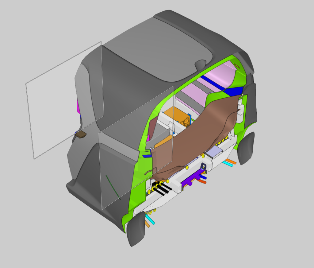
Excluding/Including a Set of Parts
To visualize a specific part of the model without isolating everything that gets cut, you can exclude a selected group from the cut.
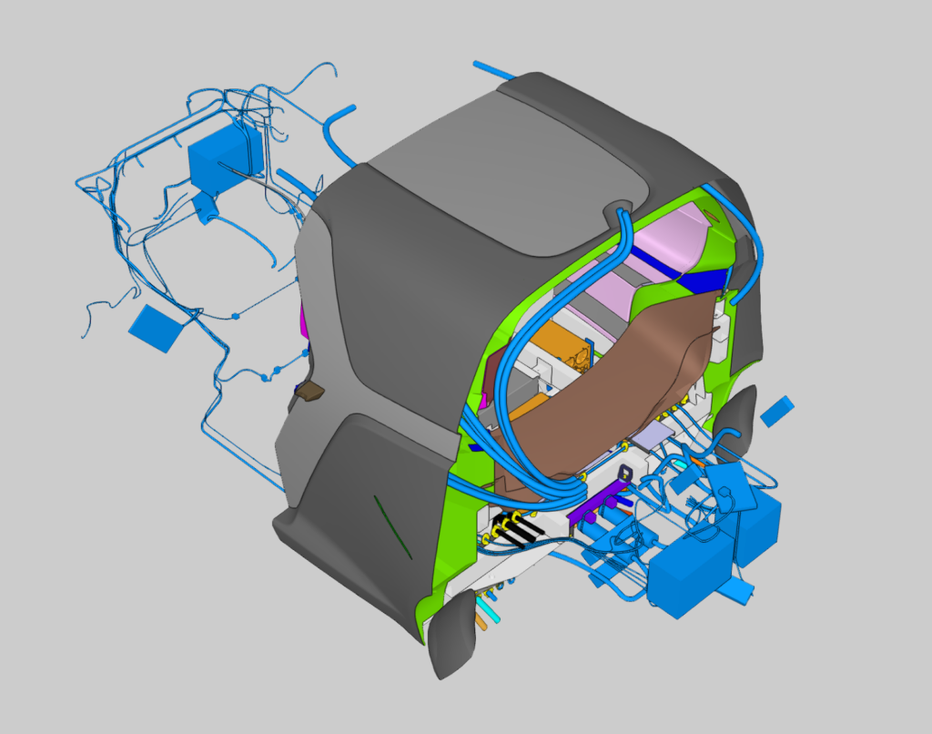
You’ll need to use layers to define a set of attributes.
To do this, create a new layer or choose an existing one, then add a filter to select a group of parts. For example, here we choose subsystems like the wiring and the interior body of the vehicle.
Use the context menu of the layer, then click on “Ignore Cut Planes,” and everything included in this filter will not be affected by the cut.
Tools & Measurements
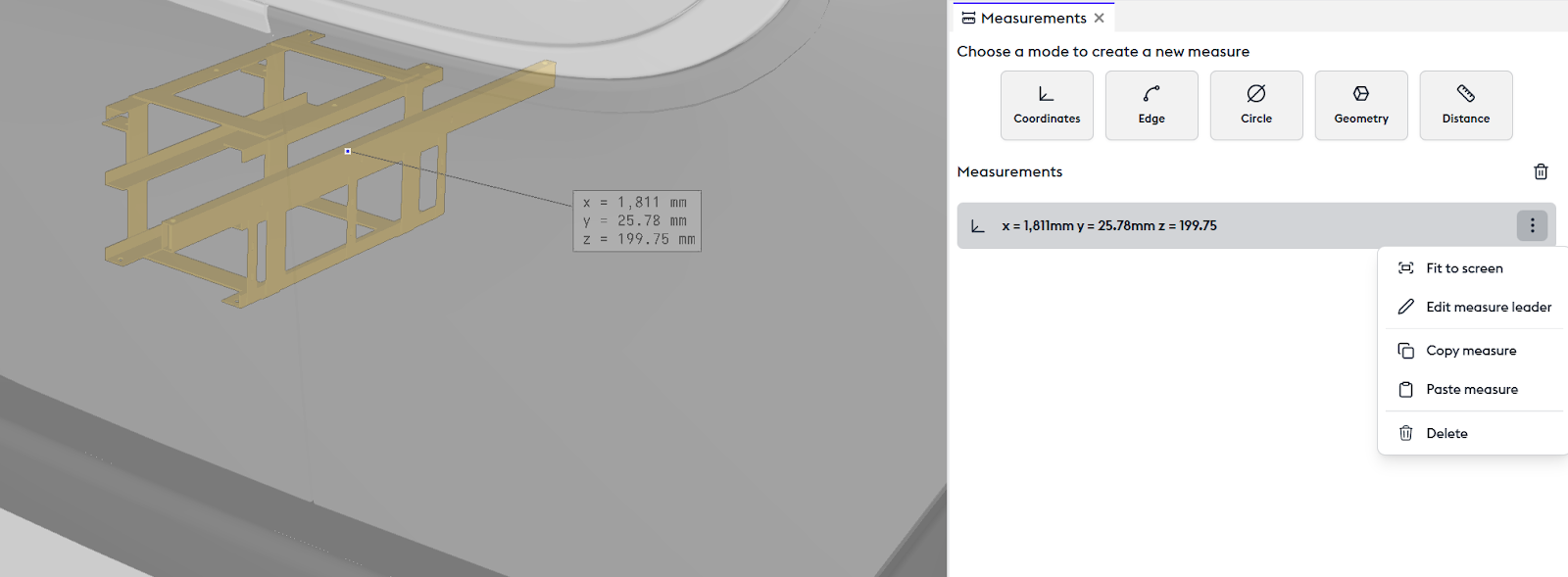
Coordinates
The Coordinates tool allows you to view the position of a point in space — these are the 3D coordinates relative to the origin (zero point). Selecting this point creates an annotation in the 3D view and a corresponding step in the measurement panel.
From this step or via a right-click on the annotation, you can choose to zoom in on this point in the 3D view (“Fit to screen“), move the annotation to a chosen location (“Edit measurement leader line“), copy the value as text (“Copy measurement“), or delete the measurement (“Delete“).
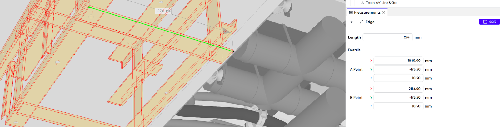
Edge
The Edge tool measures the edge of an object. When selecting the object, all its edges become selectable, allowing you to choose one of them. An annotation appears in the 3D view along with its corresponding step in the Measurements panel.
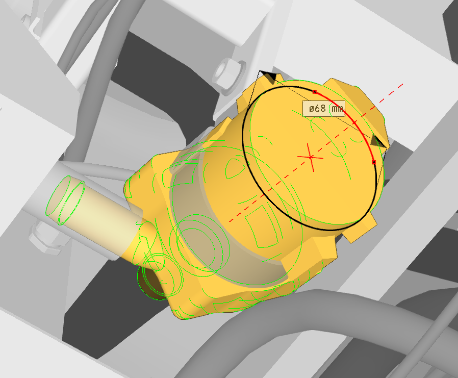
Circle
The Circle tool measures the circular diameter of a part. By selecting the part, all available circular measurements are displayed for that object.
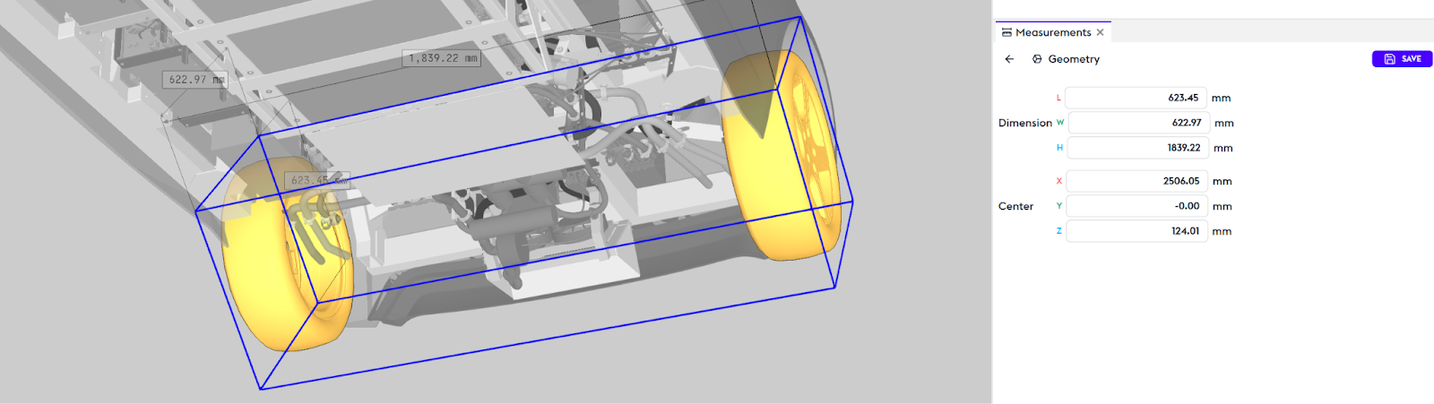
Geometry
The Geometry tool is used to measure the overall dimensions of a part: length, width, and depth.
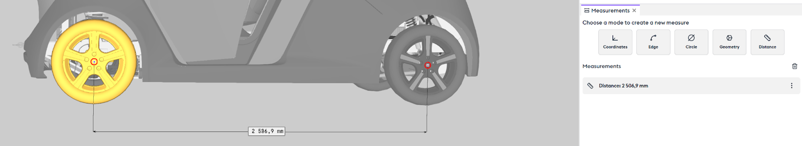
Distance
The Distance tool measures the distance between two objects. You can specify in the selection box whether you want to measure from point to point, edge to point, etc.
You can choose to delete the destination point to restart, or the starting point. Like all other measurements, this distance will be saved in the history.
Transformation
Introduction
The movement of parts or assemblies is managed through layers.
To move a part, you must create a layer and insert that part into a filter. For example, this car door: create a layer, filter the parts to be added into it, and then name it.
This layer is selected, and all chosen movements will be applied to this layer:
Translation
Translation allows you to move the part along its X, Y, and Z axes.
Rotation
Rotation allows you to rotate the part around its three axes.
When manipulating in 3D, the panel will display the axis and the angle of rotation (this information also appears in the 3D view).
At the end of the manipulation, you can modify the angular value in the panel. The rotation will then be updated.
However, as soon as you choose another rotation axis, a new rotation will be created, which is why the angle resets to zero. You can then enter a new value that will modify the newly created rotation.
If you are using the World mode, the center of the part is selected.
If you want to rotate around a specific point, select the Feature mode and place your point on the model.
All your actions are reversible by clicking in the history (History).
Scale
The Scale tool allows you to change the scale of the part.
Exploded
The Exploded View tool allows you to create an exploded view of a part.
The method is the same—let’s take the braking system as an example.
The Boxing Filter
It’s useful here to revisit the concept of the box filter.
In the example, metadata considers both braking assemblies as a single part.
If you want to illustrate only one braking assembly, you should use a box filter to select only the left braking system, for example.
About boxing filters:
During the creation of your box filter, all transformations applied to parts of the model (including those on other layers) will be disabled for the duration of the box creation.
Align
The Align tool allows you to automatically align one part with another by selecting any edge of the part.
For example, let’s take a brake mounting nut. We create a layer containing it.
Since several nuts seem to have the same name, you need to add a box filter to act only on this specific part.
In our example, we move it using a translation and a rotation. Then, we choose to align it with its original hole by selecting the origin—here, the circle—then selecting the target—here, the hole—and the alignment will be performed automatically.
You can fine-tune it using the offset.